Designing an FSM Controller and Simulating in Logism
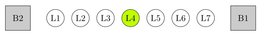
We will use 7 LEDs and two buttons for two players. The game starts with the led in the middle turned on. One user tries to shift the ON led to left while the other tries to push it to right. The one pushing the button faster wins the game.
TL;DR: final logism circuit downloadable file
This will be a game implementation. In this game, we will use 7 LEDs and two buttons for two players.
The game starts with the LED in the middle turned on.
One user tries to shift the ON LED to the left, while the other tries to push it to the right.
The one pushing the button faster wins the game. Winning occurs when the turned-on LED reaches either the rightmost or leftmost position.
We should also consider cases when both players push the buttons at the same time or they do not push at all.
Our FSM controller has:
- Two button inputs:
B1,B2 - Seven outputs, one for each LED
- A
resetinput to start a new game
I started by drawing how the game will look when it finishes and naming the components. That looks like the image at the top.
The LED moves next when the button is released. Implementing the FSM this way would make the diagram complicated, since there must be a wait state for every button and extra transitions to consider.
Therefore, I decided to implement another controller for buttons. This controller is responsible for sending 1 for only one clock period at the moment a button is pressed.
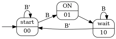
State diagram of the buttons
Truth Table of Button Controller
| s1 | s0 | B | n1 | n0 | o |
|---|---|---|---|---|---|
| 0 | 0 | 0 | 0 | 0 | 0 |
| 0 | 0 | 1 | 0 | 1 | 0 |
| 0 | 1 | 0 | 1 | 0 | 1 |
| 0 | 1 | 1 | 1 | 0 | 1 |
| 1 | 0 | 0 | 0 | 0 | 0 |
| 1 | 0 | 1 | 1 | 0 | 0 |
From the truth table we can see that o (output) is the same as n1.
Thus, we can use n1 as the output.
n1 = s1’ s0 + s1 s0’ B
n0 = s1’ s0’ B
Final Button Circuit
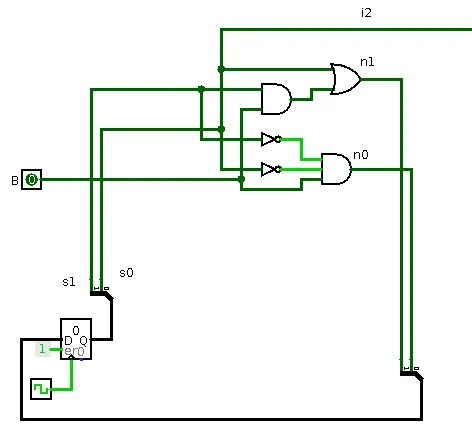
Circuit design of button
Drawing State Diagram
There are two inputs coming from the output of the button controller (captures the moment of button release):
i1→ button 1i2→ button 2
For states L2, L3, L4, L5, L6:
- As long as both buttons are pressed or both buttons are not pressed, the FSM stays in the same state.
- This behavior is represented using XNOR (⊙).
For states L1 and L7, only the reset button is considered.
When reset is pressed, the FSM goes back to the initial state L4.
There are 7 states, which can be represented using 3 bits.
Since the initial state is L4, it is labeled as 000.
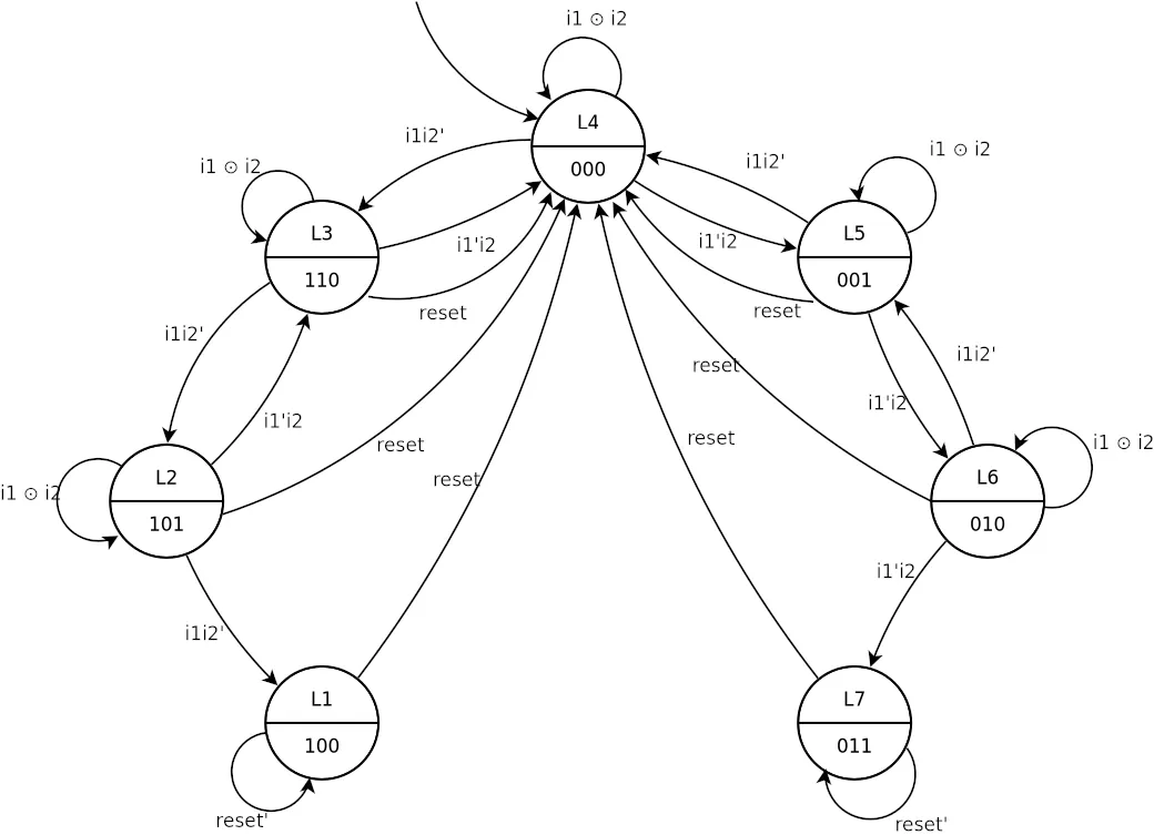
State diagram of the FSM
Truth Table
There are:
- 3 bits for current state
- 2 input bits
- 1 reset button
That would make 6 inputs total, resulting in 64 rows in the truth table.
To simplify the design and reduce the number of gates, the reset button is not included in the truth table. Instead, reset is connected directly to the clear pin of the state register, forcing the FSM to return to the initial state whenever reset is pressed.
| s2 | s1 | s0 | i2 | i1 | n2 | n1 | n0 |
|---|---|---|---|---|---|---|---|
| 0 | 0 | 0 | 0 | 0 | 0 | 0 | 0 |
| 0 | 0 | 0 | 0 | 1 | 1 | 1 | 0 |
| 0 | 0 | 0 | 1 | 0 | 0 | 0 | 1 |
| 0 | 0 | 0 | 1 | 1 | 0 | 0 | 0 |
| 0 | 0 | 1 | 0 | 0 | 0 | 0 | 1 |
| 0 | 0 | 1 | 0 | 1 | 0 | 0 | 0 |
| 0 | 0 | 1 | 1 | 0 | 0 | 1 | 0 |
| 0 | 0 | 1 | 1 | 1 | 0 | 0 | 1 |
| 0 | 1 | 0 | 0 | 0 | 0 | 1 | 0 |
| 0 | 1 | 0 | 0 | 1 | 0 | 0 | 1 |
| 0 | 1 | 0 | 1 | 0 | 0 | 1 | 1 |
| 0 | 1 | 0 | 1 | 1 | 0 | 1 | 0 |
| 0 | 1 | 1 | 0 | 0 | 0 | 1 | 1 |
| 0 | 1 | 1 | 0 | 1 | 0 | 1 | 1 |
| 0 | 1 | 1 | 1 | 0 | 0 | 1 | 1 |
| 0 | 1 | 1 | 1 | 1 | 0 | 1 | 1 |
| 1 | 0 | 0 | 0 | 0 | 1 | 0 | 0 |
| 1 | 0 | 0 | 0 | 1 | 1 | 0 | 0 |
| 1 | 0 | 0 | 1 | 0 | 1 | 0 | 0 |
| 1 | 0 | 0 | 1 | 1 | 1 | 0 | 0 |
| 1 | 0 | 1 | 0 | 0 | 1 | 0 | 1 |
| 1 | 0 | 1 | 0 | 1 | 1 | 0 | 0 |
| 1 | 0 | 1 | 1 | 0 | 1 | 1 | 0 |
| 1 | 0 | 1 | 1 | 1 | 1 | 0 | 1 |
| 1 | 1 | 0 | 0 | 0 | 1 | 1 | 0 |
| 1 | 1 | 0 | 0 | 1 | 1 | 0 | 1 |
| 1 | 1 | 0 | 1 | 0 | 0 | 0 | 0 |
| 1 | 1 | 0 | 1 | 1 | 1 | 1 | 0 |
Boolean Expressions
Logisim can show simplified Boolean expressions directly from the truth table using:
Window → Combinational Analysis
Simplified expressions:
n2 = s1’s0’i2’i1 + s2s1’ + s2i2’ + s2i1
n1 = s2’s1’s0’i2’i1 + s0i2i1’ + s2’s1i1’ + s1i2’i1’ + s1i2i1 + s1s0
n0 = s2’s0’i2i1’ + s0i2’i1’ + s0i2i1 + s1i2’i1 + s1s0
Schematic on Logisim and Testing
After combining all components, the circuit works flawlessly, with one requirement:
To transmit the status, the button or pin must be active when the rising edge of the clock arrives.
I used 7 LEDs and AND gates to display the current state:
- Inputs:
n2,n1,n0(or their inverses) - Output: the corresponding LED
Test Cases
- Both buttons pressed → state remains unchanged
- One button pressed while the other is rapidly pressed and released → LED shifts correctly, faster player wins
- Reset pressed at intermediate stages → game resets to initial state
(Pins were used instead of physical buttons for testing.)